Logic Gates and Boolean Algebra
Introduction to AND, OR, NOT, XOR gates.
Introduction
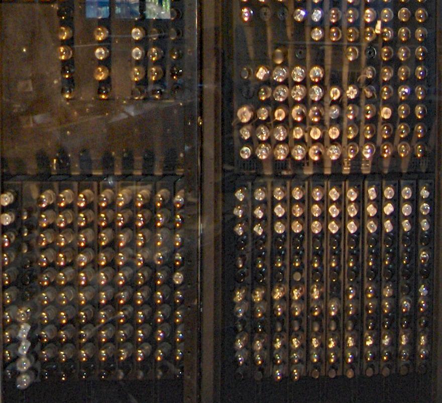
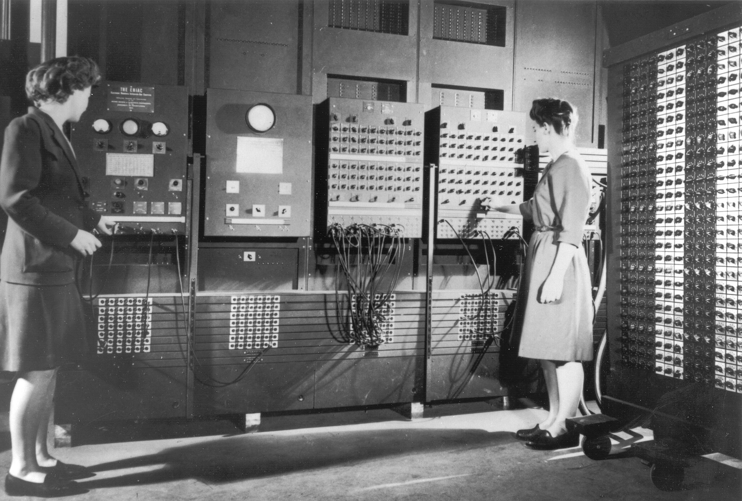
In 1946, the world’s first programmable electronic computer was created: the ENIAC (Electronic Numerical Integrator and Computer). It was a massive machine, filling an entire room with thousands of vacuum tubes, and yet it laid the foundation for every modern computer we use today.
The ENIAC was programmed by a pioneering group of women, including Betty Jean Jennings and Fran Bilas, at the School of Electrical Engineering. During World War II, these women developed an expertise in programming and operating the machine. Their skills became so valuable that they were difficult to replace, even when soldiers returned from the war.
The ENIAC used vacuum tubes as switches to amplify or switch off the electricity in order to store bits, flip bits, and perform Boolean operations. This allowed the ENIAC to perform basic math and help with calculations.
Logic gates are the fundamental building blocks of digital circuits. They take simple inputs (like 0s and 1s) and combine them using basic rules (AND, OR, NOT, XOR) to produce outputs. From these simple operations, computers can add numbers, compare values, store information, and eventually run complex software.
By studying logic gates, we connect the concepts seen in binary to electronic hardware.
- In the early days of computing, there was a job called being a computer, where women, mostly women, some men, would calculate and compute. During World War II, there was a large need for mathematical solutions (…)
-
Megan Smith, U.S. Chief of Technology
::: {layout-ncol=2}
Logic in electronics
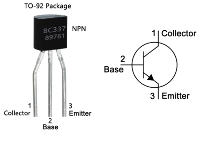
Processors work by reacting to an input of 0s and 1s in specific ways and then returning an output based on the decision. The decision itself happens in a circuit called a logic gate, each of which requires at least one transistor, with the inputs and outputs arranged differently by different operations. The most elemental electronic component required to make logic circuits are the transistors which we discussed in a previous lecture. These three electronic switches were invented in 1947 and revolutionized the computing world by replacing the vacuum tubes with electrical signals.

The number of transistors in an integrated circuit (IC) has historically doubled about every two years, a trend known as Moore’s Law. However, since around 2010, the pace of semiconductor advancement has slowed across the industry. This slowdown is largely due to the physical limits of transistors, as they approach sizes so small that further miniaturization becomes increasingly difficult and costly.
[Moore’s Law - The number of transistors on integrated circuit chips (1971-2018)].
Transistors
A transistor is like a tiny switch made from a semiconductor and three parts called the base, emitter, and collector. By controlling the base, we can turn the flow of current on or off—just like flipping a light switch. What makes transistors powerful is that they can switch on and off millions of times per second. When we connect many transistors together (with other components) to make electronic circuits, they form logic gates. The four basic gates you should know:
ORANDNOTXOR: Exclusive OR
You will use those operations frequently in programming! So make sure to pay attention to this part!
When combining these gates (AND, OR, XOR, NOT), computers can make “decisions”, and perform mathematical operations like addition or more complex tasks such as multiplexing.
Each logic gate will take one or more bits as input and return an output. To describe the behaviour of each we will look at their truth table, which list all the possible outcomes of this gate.
Let’s first understanding them from a conceptual level using simple “True” (1) or “False” (0) statements and watch the output of each gate.
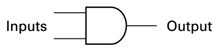
AND Gate
An “AND” is a conjunction of two inputs. It returns whether both are true at the same time.
For example: Shrek is an ogre AND Fiona is a princess, both statements are true, therefore the entire statement is true. If one of them was false, the entire statement is incorrect.
The “AND” gate will return 0 in any other combination. For example:
It’s Tuesday today AND it’s raining, if today is really Tuesday but not raining, this statement is false. Both statements must be correct for the output of the AND gate to be true.
It’s Friday today AND it’s the weekend, this statement is false because Friday is a week day, we cannot be on the weekend if today is Friday. The “AND” makes this entire statement false.
Symbol

Truth Table
A truth table lists out all the independent possibilities of inputs and sets the output of a logic circuit. In the case of the AND gate, the logic gate is straightforward, only if the two inputs are at 1, the output will be 1. All other possibilities are 0.
Truth Table
| Input 1 | Input 2 | Output |
|---|---|---|
| 0 | 0 | 0 |
| 1 | 0 | 0 |
| 0 | 1 | 0 |
| 1 | 1 | 1 |
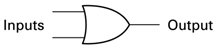
OR Gate
The “OR” gate is less “strict” than the “AND”, if either of the two inputs or both are true (1), the output is (1). This is what we call a disjunction. Let’s look at an example:
To be healthy you must either train OR eat a lot of vegetables.
This statement is true if a person trains without eating vegetables, if a person eats vegetables but doesn’t train, or does both. But it won’t be true if a person doesn’t train and doesn’t eat protein.
Symbol
The OR gate has two inputs:
Truth Table
| Input 1 | Input 2 | Output |
|---|---|---|
| 0 | 0 | 0 |
| 1 | 0 | 1 |
| 0 | 1 | 1 |
| 1 | 1 | 1 |
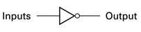
NOT Gate
The not gate simply inverts a bit and has only one input. If it’s 1 (true), it becomes 0 (false) and vice versa. Here is an example:
My automatic LED turns ON, when the ambient light is low and turns OFF when the ambient light is high.


Symbol
The NOT has only one input:
Truth Table
| Input | Output |
|---|---|
| 0 | 1 |
| 1 | 0 |
XOR Gate
The XOR gate, or exclusive OR takes two inputs and returns true only if both inputs are different. For example:
Today is Tuesday or Thursday, this statement is false if today is neither Tuesday nor Thursday. This statement is false if both are true (because in this case they are mutually exclusive). It’s only true if today is really a Tuesday or if it’s a Thursday.
Symbol
The XOR has two inputs, in this case A and B:
XOR Truth Table
| Input 1 | Input 2 | Output |
|---|---|---|
| 0 | 0 | 0 |
| 1 | 0 | 1 |
| 0 | 1 | 1 |
| 1 | 1 | 0 |
More complex gates
These basic gates can allows us to construct more complex gates that perform more complicated operations. Here are a few examples.
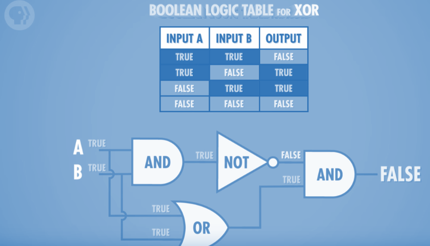
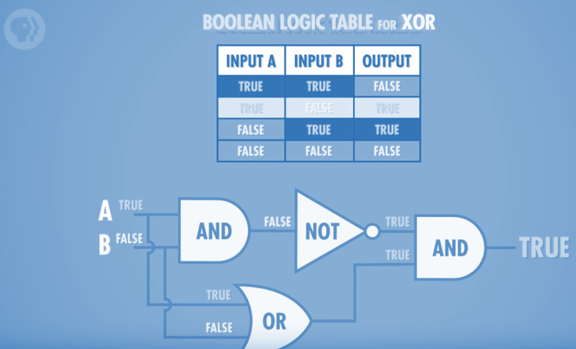
XOR
Although presented as a simple gate, the XOR is actually more complex and involves connecting multiple AND, OR and NOT gates together as such:
Half-Adder
The half adder is a circuit which adds two bits together and keeps track of the Sum and the Carry (i.e. the new power of 2 that carries over). For example:
- 0 + 0 = 0(Carry) 0 (Sum)
- 1 + 0 = 0 1
- 0 + 1 = 0 1
- 1 + 1 = 1 0
The truth table of this gate is:
| A | B | C | S |
|---|---|---|---|
| 0 | 0 | 0 | 0 |
| 1 | 0 | 0 | 1 |
| 0 | 1 | 0 | 1 |
| 1 | 1 | 1 | 0 |
We can achieve this gate by using a XOR gate for the Sum and an AND gate for the Carry.

Full-Adder
The problem with the half-adder is that it doesn’t account for the Carry over from a previous addition. As we have seen in class, when adding two binary numbers we start from the lowest powers and keep must track of the carry over power to the next power of 2, and repeat the addition with the higher powers.
From Logic Circuits to CPUs
We will learn very soon, that the CPU is made of a Arithmetic logic unit which is made up entirely from logic circuits such as the ones we have seen so far. The logic circuits of the CPU will determine the bus width of the system (ex: 64-bits).
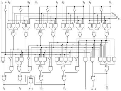
These CPUs are capable of performing the following operations:
- Add
- Add with Carry
- Subtract
- Subtract with borrow
- One’s complement
- Two’s complement
- Increment
- Decrement
- Pass through
- Logical operations (AND, OR, XOR, NOT)
- Bit shift operation
Boolean Algebra
Integrated circuits (microchips) are used to store and process information in the form of bits. These bits can be manipulated using Boolean operations, which are based on Boolean algebra named after, named after the mathematician George Boole.
In Boolean systems, a variable can take on only two values: 0 (false) or 1 (true). By applying Boolean operations, we can manipulate one or more of these values. Boolean algebra is especially important in the analysis and synthesis of logical expressions, making it the foundation for how digital circuits and computers work.