Electronics Basics#
Why study electronics?#
This course is at the boundary of code and physical objects. While we access the GPIOs of our reTerminals using filesystems and code, ultimately the digital signals are being delivered with electricity along conductive physical components.
Having a basic understanding of electronics will help you properly connect and debug digital devices without damaging them.
GPIO Physical Limits#
The reTerminal has the following electrical constraints (see official wiki):
An individual GPIO pin in the reTerminal can only safely draw 16mA current.
GPIO pins can only handle 3.3V voltage.
The power pins (3.3V and 5V) can handle a maximum of 2A current.
What do these numbers mean? Why does it matter for us? What can we do about it?
Units of Measurement: Volt, Amp, and Ohm#
Bellow are the basic units that are used to measure electricity:
Quantity |
Symbol |
Unit |
Abbreviation |
|---|---|---|---|
Current |
I or i |
Ampere (“Amps”) |
A |
Voltage |
V or E |
Volts |
V |
Resistance |
R |
Ohm |
Ω |
An electric circuit is formed when a conductive path is created to allow electric charge to continuously move.
Current#
The movement of electric charge (electrons) through the conductors of a circuit is called a current, and it is often referred to in terms of “flow,” just like the flow of a liquid through a hollow pipe.
Voltage#
The force pushing the electrons to “flow” in a circuit is called voltage.
Voltage is a specific measure of potential energy that is always relative between two points. This is comparable to the pressure pushing water from a reservoir into a pipe.
Voltage relates to the amount of potential energy between two points.
Without reference to two relative points, the term “voltage” has no meaning.
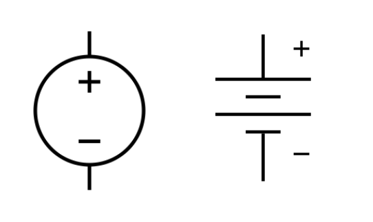
Voltage is added to a circuit by a voltage source, such as a batter or a power supply unit attached to a wall.
Below are the two symbols typically used to identify a voltage source in a circuit:
Resistance#
Current moves through the conductors with some degree of friction, or opposition to motion. This opposition to motion is more properly called resistance.
The amount of current in a circuit depends on the amount of voltage and the amount of resistance in the circuit to oppose current flow.
Just like voltage, resistance is a quantity relative between two points.
Voltage and resistance are often stated as being “between” or “across” two points in a circuit.
Below are the two symbols used for a resistor:

Ohm’s law#
Ohm’s law describes the relationship between voltage, current and resistance.
The amount of current through a metal conductor is directly proportional to the voltage across it.
V = IR
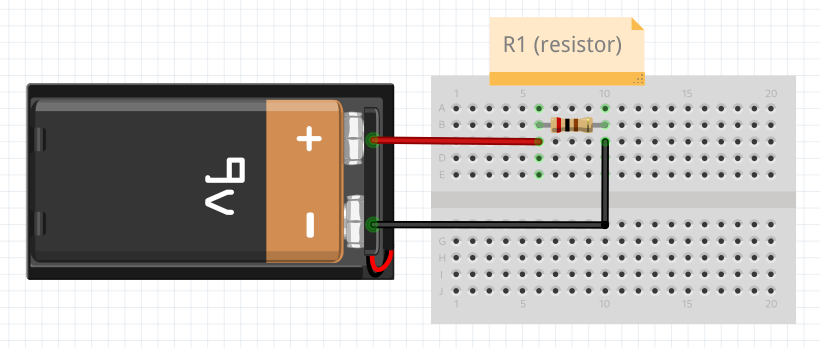
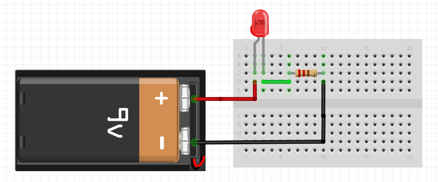
Consider the following circuit:
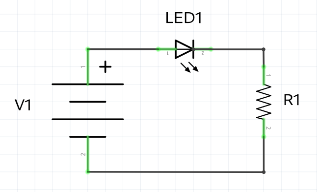
The proper circuit diagram will be:
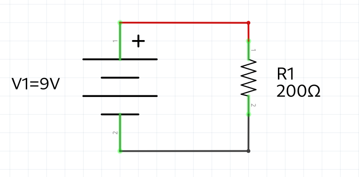
If V1=9V and R1 = 200Ω, what is the current running through the circuit?
Rearranging Ohm’s law we get:
I=V/R
Therefore:
I = 9V / 200Ω = 0.045A (amps) or 45mA (milli amps).
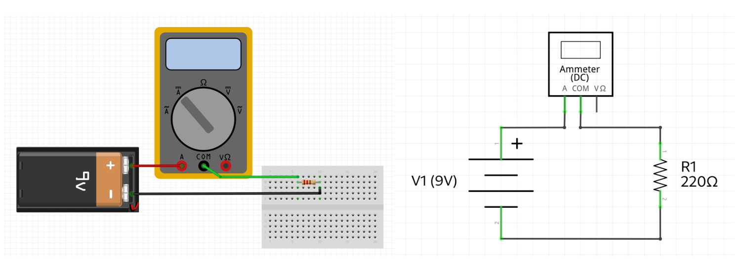
We can measure the current by using a multimeter in “ammeter” mode.
The multimeter must be added in series with the circuit. This means that the wiring must “go thorough” the multimeter.
Voltage Drop Across Components#
Consider the circuit below:
We must select the resistor value in order to maximize the life of the LED.
The following requirements apply:
The ideal current across the LED is of 20mA.
The voltage drop across the LED (Vled) is of 2.2V.
The voltage source is 12V.
Using Ohm’s law:
R1 = Vr / Ir (Vr and Ir are the voltage and current across the resistor)
How do we find Vr and Ir?
Note that because there is a LED that is also “consuming” some voltage, R1 is no longer the same as V1.
The total voltage drop across all components of the circuit must equal the source voltage.
This is know as Kirchhoff’s Law
This means that the voltage dropped at the LED and the resistor must add up to the same value as the source voltage.
V1 = Vled + Vr
Vled was provided as a design constraint: Vled = 2.2V. Therefore we can easily calculate Vr:
Vr = V1 - Vled = 12V - 2.2V = 9.8V
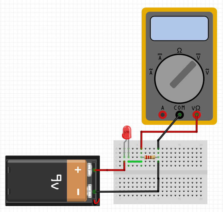
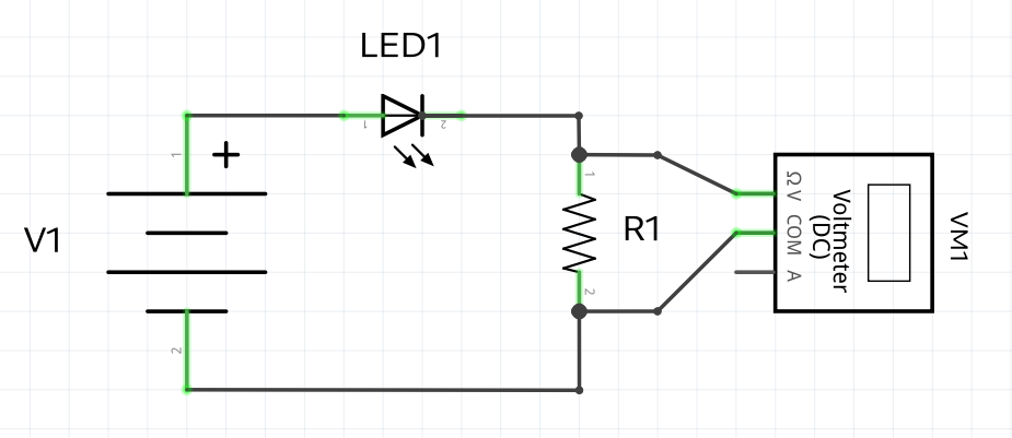
It’s possible to measure the voltage drop across the resistor by using a multimeter that measures the voltage difference before and after the resistor.
Notice how the multimeter is not interrupting the circuit. It is rather “sampling” the circuit at two points.
Now that we know the voltage drop across the resistor, we are only missing the current flowing through it (Ir)
Because the circuit only has a single path, the current leaving the source is the same as the current flowing through all components.
Since we are optimizing for the LED lifespan, the target current is 20mA or 0.02A.
We now have all necessary information to calculate the resistance value:
R1 = Vr / Ir = 9.8V / 0.02A = 490Ω
Resources & References#
Ohm’s Law - How Voltage, Current, and Resistance Relate by All About Circuits
Voltage Divider Circuits by All About Circuits