GPIOs: Inputs and Outputs#
Intro to Pi’s GPIOs 🥧#
Note: most of these notes were adapted directly from the Raspberry Pi docs: GPIO-Pinout 1Raspberry Pi documentation is copyright © 2012-2024 Raspberry Pi Ltd and is licensed under a Creative Commons Attribution-ShareAlike 4.0 International (CC BY-SA) licence. Some content originates from the eLinux wiki, and is licensed under a Creative Commons Attribution-ShareAlike 3.0 Unported licence.
The Raspberry Pi can read and generate digital signals using General Purpose Input and Output (GPIO) pins.
Any of the GPIO pins can be designated (in software) as an input or output pin and used for a wide range of purposes.
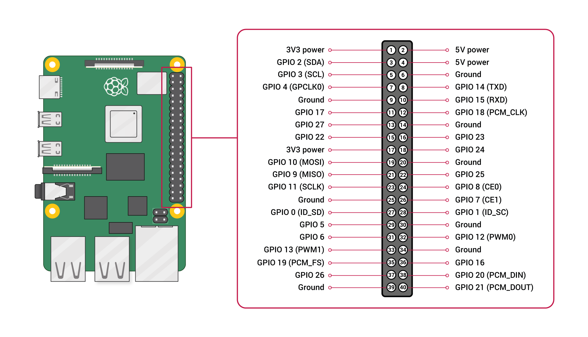
GPIO and the 40-pin headers of the Raspberry Pi - Official docs, Raspberry Pi Foundation.
The reTerminal exposes the same 40-pin header as the Pi on it’s side:
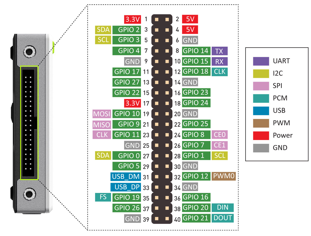
GPIO and pin diagram of the reTerminal - reTerminal Official Wiki, Seeed.
Voltages#
Two 5V pins and two 3V3 pins are present on the board, as well as a number of ground pins (0V), which are unconfigurable. The remaining pins are all general purpose 3V3 pins, meaning outputs are set to 3V3 and inputs are 3V3-tolerant.
Outputs#
A GPIO pin designated as an output pin can be set to high (3V3) or low (0V).
Inputs#
A GPIO pin designated as an input pin can be read as high (3V3) or low (0V).
We will learn how to use the GPIOs in a future lesson.
Digital Communication Protocols#
In addition to simple input and output devices, the GPIO pins can be used with a variety of alternative functions and digital communication protocols.
These digital communication protocols are:
PWM (pulse-width modulation)
SPI (serial peripheral interface)
I2C (inter-integrated circuit)
Serial
PCM (pulse-code modulation)
Some digital functions are available on all pins, others on specific pins.
Sorry, No Analog#
The Raspberry Pi does not have an ADC.
In order to process analog electrical signals an external ADC must be used.
Hat to the Rescue
In this course we will use the integrate ADC of the Grove Base Hat for the Raspberry Pi.

Seeed's Grove Base Hat for the Raspberry Pi has an integrated ADC Base Hat official wiki, Seeed.
Pi HATs is the term for expansion boards for the Raspberry Pi.
Seeed’s Grove Base Hat for the Raspberry Pi has 4 connectors with integrated ADC.
Each ADC connector has 12-bit resolution.
In addition to the 4 ADC connectors, the Base Hat also exposes the original 40-pin header and other digital connectors.

Specialized connectors of the Raspberry Pi available via the Base Hat Base Hat official wiki, Seeed.
GPIO pinout#
A GPIO reference can be accessed on your Raspberry Pi by opening a terminal
window and running the command pinout. This tool is provided by the
GPIO Zero Python library, which is installed
by default in Raspberry Pi OS.
$ pinout
Important
While connecting up simple components to the GPIO pins is perfectly safe, it’s important to be careful how you wire things up. LEDs should have resistors to limit the current passing through them. Do not use 5V for 3.3V components. Do not connect motors directly to the GPIO pins, instead use an H-bridge circuit or a motor controller board.
Permissions#
In order to use the GPIO ports, your user must be a member of the gpio group.
The default user account is a member by default, other users need to be added
manually.
# Only do this to add a NEW user to the gpio group
sudo usermod -a -G gpio <username>
GPIO in Python#
Using the GPIO Zero library makes it easy to control GPIO devices with Python. The library is comprehensively documented at gpiozero.readthedocs.io.
LED#
To control an LED connected to GPIO17:
from gpiozero import LED
from time import sleep

led = LED(17)

while True:
    led.on()
    sleep(1)
    led.off()
    sleep(1)
LED methods include on(), off(), toggle(), and blink().