ReTerminal Kit#
In this course, you are provided with a reTerminal kit containing hardware for experimenting with electrical devices on a portable Linux system.
This document will be a reference for any information you need to know about the various devices you have been provided.
reTerminal#
Most of the information from the following sections was scraped from [@GettingStartedReTerminal2023]
The reTerminal is a development board based on the Raspberry Pi Compute Module 4 (CM4) manufactured by Seeed Studio.
See reTerminal Wiki page for the complete specs and documentation
Features#
Integrated modular design with high stability and expandability
Powered by Raspberry Pi Computer Module 4 with 4GB RAM & 32GB eMMC
5-Inch IPS capacitive multi-touch screen at 1280 x 720 and 293 PPI
Wireless connectivity with dual-band 2.4GHz/5GHz Wi-Fi and Bluetooth 5.0 BLE
High-speed expansion interface and rich I/O for more expandability
Cryptographic co-processor with secure hardware-based key storage
Built-in modules such as accelerometer, light sensor and RTC
Gigabit Ethernet Port and Dual USB 2.0 Type-A ports
40-Pin header for IoT applications
See Specifications on the reTerminal wiki webpage for a complete table of device specifications.
Chassis#
The chassis of the reTerminal is the external “case” of the entire device. The image below shows all of it features: a touch screen, buttons, LEDs, ports, and more.

The chassis of the reterminal CM4.#
Motherboard#
The “desktop” hardware of the reTerminal is shown in the figure below. The usual desktop computer elements (CPU, RAM, Power, Ethernet, USB, etc.) are all here.
In addition, we can see reTerminal-specific features: touch screen interface, camera ports, an accelerometer, and more.

Motherboard diagram for the reTerminal CM4.#
Compute Module 4#
The raspberry pi Compute Module (CM) 4 made by the Raspberry Pi Foundation is the main computing device that powers the reTerminal.
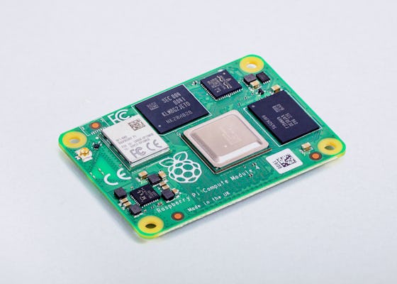
Raspberry PI CM 4#
RaspberryPi has published a very detailed datasheet for the CM4 that we will refer to frequently in this course – take a look!
Pinout Diagram#
The reTerminal offers a 40 pin interface for the GPIO ports of the raspberry pi CM4. The “Pinout” diagram is a map indicating which port corresponds to which GPIO interface on the CM4.

Pinout diagram for the reterminal CM4 GPIO ports. Pay attention to the orientation of the reTerminal in the above diagram. The LCD and the onboard buttons are on the right-hand side of this image, the back of reTerminal is on the left-hand side, and the onboard buttons are on the top.#
Block Diagram#
We can also reTerminal features via a block diagram, shown below:

Block diagram for the reTerminal, indicating the communication protocols required for accessing each of the reTerminal features. This diagram will be more useful once we study electronics communication protocols.#
Grove Base Hat for Raspberry Pi#
In a typical Raspberry Pi, sensors would be connected via the 40-pin GPIO. To facilitate connections of the Grove sensors, this “Hat” (term for an add-on board of the Raspberry Pi) includes the following types of connection:
6 Digital
4 Analog
3 I2C
1 PWM
1 UART

Grove Base Hat for GPIO connections#
See Grove base hat Wiki for details.
Power Supply for Raspberry Pi#
The reTerminal requires a power supply that can provide a minimum of 3 Amps.

RPI power supply#
The official Raspberry Pi USB-C Power Supply is included in your kit.
Sensors#
Sensors are devices that measure phenomenon in the external world. We will work with many sensors in this course.
The sections below describe the sensors that are included in your reTerminal kit.
AHT20 I2C Temperature & Humidity Sensor#
The AHT20 is a combined temperature and humidity sensor that communicates over GPIO using the I2C protocol.

AHT20 I2C temperature/humidity sensor#
See AHT20 I2C Industrial Grade Temperature & Humidity Sensor wiki for details.
Temperature measurement range -40 ~ 85°C, Humidity measurement range 0 ~ 100% RH.
Digital output, Grove I2C interface.
Actuators#
Actuators are controllable devices that change phenomenon in the external world. We will work with many actuators in this course.
The sections below describe the actuators that are included in your reTerminal kit.
LED Socket#
An LED in a removable socket with a potentiometer for power adjustment. LED can be swapped with different colors.

The LED socket actuator with a red LED in the socket.#
See LED wiki page for details.
Cooling Fan#
5V Cooling Fan 40mm x 10mm with 2-pin JST connector. See product page here.
Relay#
A digital switch. Controls the on/off flow of electricity with a small digital signal.
Operate voltage: 3.3V-5V
Input current: 100mA
Rated load: 5A@250VAC 5A@30VDC
See relay wiki page for details.
Cables#
The following cables are included in the base kit:
40-pin flat ribbon cable 20cm (female-female).
2-pin JST SM Plug, one end open.